
Chip-Off Data Recovery Protocols: Raw Dump Extraction and Rebuilding Firmware Algorithms on Corrupted Flash Controllers
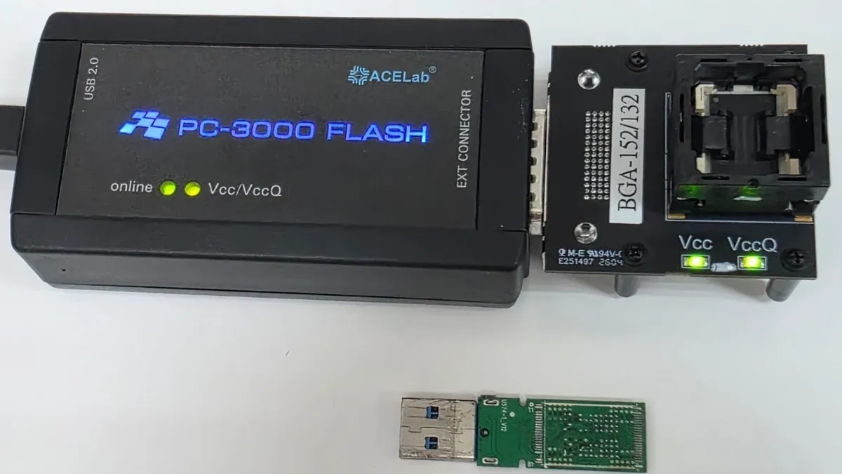
USB Flash Drives consist of a printed circuit board (PCB) housing a primary controller and a NAND flash memory chip. When the controller suffers electrical damage or firmware corruption, the device stops responding over the standard USB interface, preventing the operating system from accessing logical block addresses (LBA).
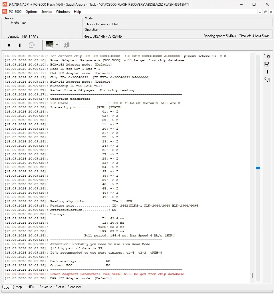
Chip-Off data recovery is the engineering procedure designed for these failure scenarios. It involves physically removing the memory chip from the PCB and reading its raw contents directly using specialized hardware readers. This article outlines the step-by-step process of this technical procedure using a USB Flash Drive built with an Innostor IS918M controller and a BGA-152 memory chip carrying Chip ID 0x2CC40832.
Engineering Principles of Flash Storage and the Chip-Off Concept
Under normal operation, a flash controller such as the Innostor IS918M manages host read and write requests. It routes data through internal transformations, including XOR data scrambling to prevent cell wear, page structure allocation, Bad Block Management, and Error Correction Code (ECC) generation. Consequently, data is written across raw NAND memory cells in a scrambled, non-linear sequence.
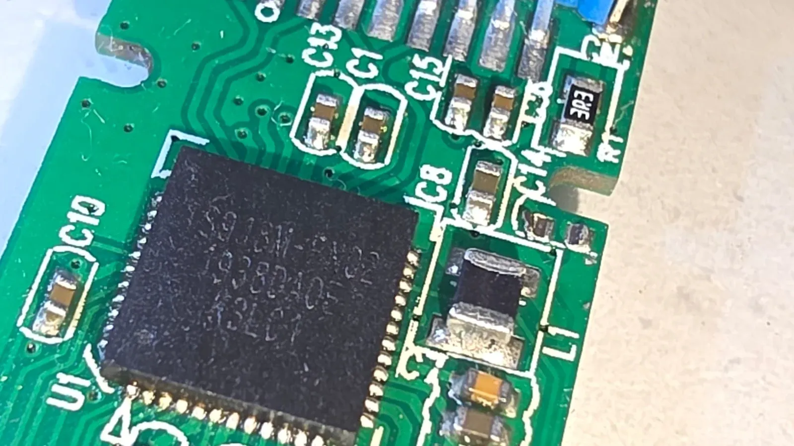
When the controller fails, the raw physical data remains intact inside the BGA-152 memory cells but becomes logically fragmented and inaccessible. The objective of Chip-Off recovery is to bypass the failed controller completely, extract a complete raw dump file, and programmatically reverse all controller transformations to reconstruct the original file system.
Failure Symptoms and Diagnosing Storage Drive Faults
Flash storage media driven by Innostor IS918M controllers exhibit distinct symptoms when controller-level failure occurs:
- Operating systems prompt the user to format the drive upon insertion.
- Disk Management displays the device as unallocated space with a capacity of
0 MB. - System freezing or input/output (I/O) device errors occur during access attempts.
Distinguishing Electrical Failures From Firmware Corruption
Professional diagnosis distinguishes between two main failure modes:
- Printed Circuit Board (PCB) Electrical Failures: Caused by blown surface-mount fuses, failed capacitors, or damaged voltage regulators. In these cases, both the controller and memory chips remain physically undamaged.
- Controller Firmware Corruption: Occurs when the controller cannot load its translator tables from the Service Area (
SA). The controller enters a locked or panic state, severing logical communication with the host.
Safe Handling Practices and Actions That Worsen Damage
Handling drives with controller failures requires strict precautions to avoid permanent data destruction:
- Avoid repeated power cycles. Unstable power delivery can cause further degradation to weakened NAND cells.
- Do not attempt repair using factory Mass Production Tools (MPTools) or low-level format utilities. These tools reflash controller firmware and initialize NAND memory, permanently erasing all stored user data.
- Avoid uncontrolled thermal desoldering with uncalibrated heating tools. Excessive heat warps the thin
BGA-152substrate and destroys internal silicon die connections.
The Engineering Steps of the Chip-Off Recovery Process
Thermal Desoldering of the BGA-152 Chip and Contact Cleaning
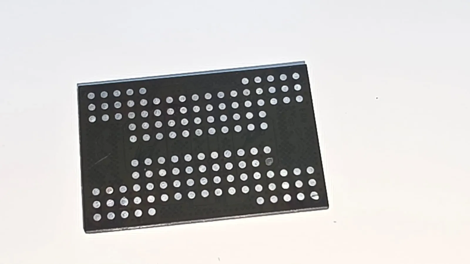
Removing the memory package requires a temperature-controlled rework environment:
- Secure the USB PCB on a bottom preheating station to elevate the board temperature gradually between
150°Cand200°C, minimizing thermal stress. - Apply a hot air gun set precisely between
350°Cand380°Cover theBGA-152contact perimeter. - Lift the chip gently using tweezers once the solder spheres reach liquidus, ensuring no PCB contact pads are lifted.
- Clean the underside contact pads of the desoldered
BGA-152chip using isopropyl alcohol and fine polishing sandpaper (grit2000to2500) to remove flux residue and oxidation without applying heavy mechanical pressure.
Hardware Extraction and Verifying the Chip ID
- Insert the cleaned
BGA-152chip into a specializedBGA-152adapter cradle attached to a hardware flash reader device such as PC-3000 Flash. - Issue an identification command over the
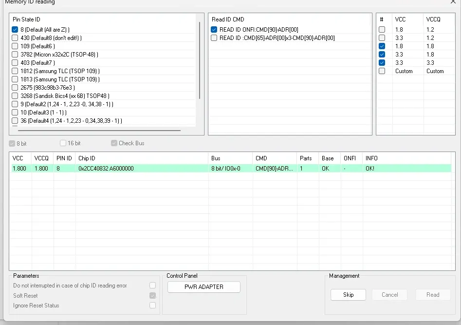
ONFIbus to read the NAND parameters. - Confirm that the hardware reader detects the correct Chip ID
0x2CC40832. This alphanumeric identifier confirms proper electrical contact, correct voltage delivery, and defines page geometry and bank structure.
ECC Error Correction and Reversing Innostor IS918M Algorithms
Once the reader extracts the raw memory contents into a .bin or .dmp image file, programmatic reconstruction begins for the single-chip, single-part NAND configuration:
- Error Correction Code (
ECC) Processing: Mathematical algorithms parse the raw dump to correct bit errors caused by degraded memory cells. - Advanced Re-reading (
Read Retry): For sectors exceeding standardECCthresholds, specializedRead Retrycommands or fine supply voltage adjustments are applied to reduce residual bit errors. XORDescrambling:Innostor IS918Mcontrollers apply a specific staticXORpattern to randomize data. The matchingInnostorXORkey is selected and applied to remove scrambling.- Page Transformation: Raw page structures are split to separate the Data Area (
DA) from the Service Area (SA) metadata.
Rebuilding the Virtual Translator and File System Reconstruction
- Scan the Service Area (
SA) of the pages to locateInnostor-specific Block Number Markers (typicallyType 1or related structures). - Order physical blocks sequentially based on marker headers to construct a Virtual Translator table, replacing the role of the physical controller.
- Align the logical structure to expose the Master Boot Record (
MBR), Partition Boot Sector, and file system tables (FAT32,exFAT, orNTFS). - Extract the user files, restoring original directory hierarchies and file attributes.
Technical Assessment and Next Steps
Successful Chip-Off data recovery depends on NAND cell integrity and accurate software reversal of Innostor IS918M controller algorithms. When a flash drive suffers controller failure, the safest technical response is to disconnect power immediately, avoid automated formatting attempts, and submit the device to a specialized recovery laboratory equipped with thermal rework tools and hardware flash readers.
Suggest next step
Need professional help?
Our experts at Al-Fares Center are ready to recover your data using state-of-the-art technology with a 95%+ success rate.